The Difference in Design between Synchronous and Asynchronous Motors

 There some difference in desigh between synchronous and asynchronous motors.

1. The biggest difference between synchronous and asynchronous motors is whether the rotor speed is consistent with the magnetic field speed of the stator. If the rotor's rotational speed is the same as that of the stator, it is called a synchronous motor. Otherwise, it is called an asynchronous motor.

2. When the number of poles is constant, there is a close connection between the motor's speed and frequency, namely, it is synchronous connection. Asynchronous motors are also called induction motors, whose rotor speed during operation is always lower than that of synchronous motors.

3. The synchronization refers to that after the current flows through the electric drive (stator) windings, a rotating magnetic field will be formed in the air gap. The rotation direction and speed of the magnetic field are the same as the rotation of the rotor. Therefore, it is synchronous. As for asynchronous motors, the rotating magnetic field and the rotor have a relative speed, namely, the torque will be generated.

Peaco Support provides a wide range of motors, including synchronous and asynchronous motors. Choose your suitable motors for your applications now.
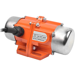
Peaco Support Motors


Comments

Popular posts from this blog

DC Contactor Relay

A contactor is an automatic switcher that is used to connect or disconnect the AC and DC main circuits or large-capacity control circuits with loads. The contactor is to control the motor and it is also used for other electrical loads, such as electric heaters, electric welding machines, lighting equipment. Contactors are very important device in industrial field, especially the high voltage DC contactors . They can not only connect and cut off the circuit, but also have a low voltage release protection. The contactor has a large control capacity, is well suitable for frequent operation and long-distance control and is one of the important components in the automatic control system. The DC contactor relay is generally used to control the DC electrical equipment. The coil is supplied with DC current. The working principle and structure of the DC contactor are basically the same as that of the AC contactor. What is the working principle of a DC contactor? When the contactor coil is ener

What is Wind Turbine?

The structure of a small wind power generation system is generally composed of a wind turbine , a generator, a rudder and an electrical control part. Conventional small wind turbines are mostly composed of induction generators or permanent magnet synchronous generators and AC/DC converters, batteries and inverters. In the blowing wind, the wind wheel rotates, turning aerodynamic energy into mechanical energy. The hub of the wind wheel is fixed on the generator shaft and the rotation of the wind wheel drives the rotation of the generator shaft, driving the permanent magnet three-phase generator to generate three-phase alternating current (AC). The wind speed changes continuously and the current and voltage generated by the generator also change accordingly. The generated electricity is rectified by the controller, is changed from alternating current (AC) to direct current (DC) with a certain voltage, make the battery charged. The direct current output from the battery pack is transforme

Why My Torque Sensor Reading is Unstable?

Torque sensors often have unstable output signals during use. But the torque sensor testing is qualified after the production. What is the reason for this? In fact, there are many reasons for the unstable signal of the torque sensor during use and the common ones mainly include the following three aspects. The torque sensor is not installed properly and the axis is not parallel, which will cause the signal output to be unstable. The torque sensor is easy to be damaged if it is in this state for a long time. The power supply voltage is unstable. Our torque sensors are generally powered by a dual voltage of plus and minus 15V and 24V or other voltages. Unstable power supply voltage will also cause unstable output signals. Interference from other machines next to the torque sensor. For example, if there is a frequency converter next to the torque sensor, it is easy to cause the output signal to be unstable. The solution is to add a 1:1 isolation transformer in front of the power supply of