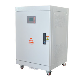
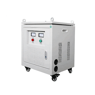
There are some difference between AC-DC-AC phase converter and frequency converter plus transformer.
Technically, phase converter features AC-DC-AC circuit structure, adopts the modulation control technology of SVPWM space vector algorithm to convert ordinary single-phase electricity to industrial three-phase electricity, which some users can not apply for due to harsh site restrictions and the single phase to three phase converters are widely applicable for various loads, such as robot arms, motors, lathes, elevators, inverters, compressors, etc.
However, frequency converter plus transformer is a power control device that uses both frequency conversion technology and microelectronics technology to control AC motors by changing the frequency of the motor's working power supply.
The detailed difference between them is shown as following.
- Usage
For phase converter, through converting single phase to three phase power, such as turning the single phase 220V to three-phase 380V power and provide a pure and stable power supply for the load. However, the other one can convert mains 220V to three-phase 380V electricity, providing power supply for the load.
- Load Type
Phase converters are suitable for various loads, such as resistive, capacitive and inductive loads. While frequency converter plus transformer are the precise control of the load speed of the motor type and it cannot be used for other loads and tests.
- Output Voltage
For phase converter, under full load conditions, the output voltage stability is 3% of the set voltage, which is not affected by load changes. On the contrary, the output voltage stability of frequency converter and transformer is 1% of the set voltage. When the load is cut off and is turned on, the voltage will rise and fall suddenly.
- Output Frequency
For phase converter, under full load conditions, the output frequency is stable and is 0.05% of the set frequency. And the other output frequency varies from the working characteristics of the motor.
- Output Waveform
Single phase to three phase converter features pure sine wave. However, frequency converter and transformer come with the wave that is similar to sine wave (long time or load change waveform distortion is large).
- Output Waveform Distortion
Under full load conditions, the output waveform distortion of phase converter is less than 2%, while the one of requency converter and transformer is less than 5%.
- EMI Interference
As for static phase converter, there is no radiation interference, low noise, low conduction interference, which can meet the requirements of laboratory equipment for power supply. However, for frequency converter and transformer, their radiation interference is low, the noise is large, the conduction interference is strong and the laboratory equipment cannot work normally.
- Control Method
The former features IPM/SVPWM method and the latter comes with IGBT/V/F control method.
- Output Method
With three-phase output, phase converter bears 20% unbalanced load. On the contrary, under three-phase load, the capacity of frequency converter and transformer is poor relatively.
- Filtering Device
The phase converter output is equipped with a special filter device, which has high output and less sub-harmonics. The frequency converter and transformer output has no filter device and there are many harmonics.
Summary
As an industrial automation company, Peaco Support phase converter provides stable and reliable three-phase power supply with professional design for various types of loads and provides standard power supply for testing to ensure the authenticity, validity and reliability of the measurement data. Peaco Support brings high quality single phase to 3 phase converters on peacosupport.com for customers worldwide.
Instead, frequency converter and transformer aim at reducing the starting current of the motors and accurately controlling the motor speed. When the load is a motor, it can meet the requirements of single-phase power to three-phase power.
 |
| Peaco Support Phase Converter |
 |
| Peaco Support Transformer |
Comments
Post a Comment